Introduction
Getting Started
Quick and short tutorial on how DGArt work.
Interface
DGArt scene and modeler interface.
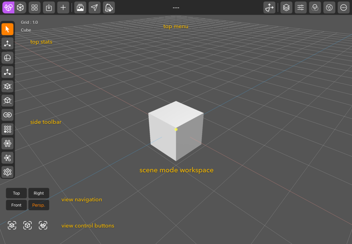
DGArt Scene Interface.
DGArt Scene Mode – Top Menu Button List (Left to Right)• Scene Mode – Default working mode for arranging and viewing your scene.
• Modeler Mode – Edit 3D objects with modeling tools.
• Project Management – Access all projects and manage file import/export.
• Save – Quickly save the current project.
• Add Objects – Add primitives, text, nodes, lights, or cameras to the scene.
• Image Library – Load external images for use as UV maps, reference images, or environmental backgrounds.
• Action Button – Includes turntable preview, screenshot capture, animation preview, and animation rendering.
• RT:Render – Render the current scene.
• Gizmo Toggle – Switch between local and world orientation for transformations.
• Layer Panel – Access the layer management panel.
• Property Panel – Access object, light, and camera properties.
• Material Panel – Access and manage materials for selected objects.
• Environment Panel – Adjust global scene settings, including background color, lighting environment, fog, and reflection settings.
• More – Access general settings, user guide, tutorials, and about information.
DGArt Scene Mode – Side Toolbar List (Top to Bottom)
• Select – When enabled, allows you to select items in the scene. When disabled, you can navigate the scene without accidentally selecting objects by touch.
• Move – Move selected items using the gizmo.
• Rotate – Rotate selected items using the gizmo.
• Scale – Scale selected items using the gizmo.
• Center Object – Center the selected object to the scene’s center point.
• Rest on Ground – Align the selected object to rest on the ground plane.
• Clone – Create a duplicate of the selected object.
• Array Clone – Clone objects in XY, YZ, or ZX planes with options for random rotation and scaling.
• Radial Clone – Clone objects in a circular pattern around a center point, with options for random rotation and scaling.
• Random Clone – Scatter clones randomly within a defined radius from the center, with random rotation and scaling options.
• Point Clone – Clone an object onto the vertices of another object. [Refer to the Points Clone link for detailed operation.]
• Delete – Delete the selected object.
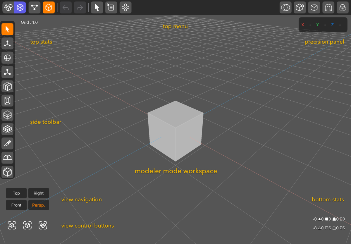
DGArt Modeler Interface.
DGArt Modeler Mode – Top Menu Button List (Left to Right)• Scene Mode – Default working mode for arranging and viewing your scene.
• Modeler Mode – Edit 3D objects using modeling tools.
• Point Edit Mode – Switch to point editing mode.
• Polygon Edit Mode – Switch to polygon editing mode.
• Undo – Undo the last operation.
• Redo – Redo the previously undone operation.
• Selection Tool – Access selection tools for points or polygons.
• Action Button – Includes Cut, Copy, Paste, Duplicate, and Delete operations.
• Mirror and Clone – Tools for Mirror (X, Y, Z), Clone, Radial Clone, and Random Clone.
• Toggle Opacity – Toggle object transparency for easier modeling.
• Add Object – Add a polygon or custom object.
• Add Reference Object – Insert a reference object into the workspace.
• Snap – Enable snapping for precise modeling and alignment.
• Assign Material – Assign a material to the selected polygons.
DGArt Modeler Mode – Side Toolbar List
• The side toolbar provides access to essential modeling tools such as Extrude, Subdivide, Cut Polygon, and more.
• Please refer to the Modeler section for detailed information on each button's function.
Navigation
Scene Navigation• Pinch to Zoom: Use a standard pinch gesture to zoom in or out.
• Tip: Hold Shift while pinching to adjust the Field of View (FOV) instead of distance.
• Two-Finger Pan: Drag with two fingers to pan across the scene.
Default Views:
• The scene provides four default viewports: Top, Right, Front, and Perspective.
View Switching via Long Press:
• Long press the Top view button to switch to Bottom view.
• Long press the Right view button to switch to Left view.
• Long press the Perspective view button to switch to Orthographic view.
View Control Buttons:
• Reset View: Resets the current view to its default position.
• Frame Object: Focuses the camera on the selected object.
• Frame All Objects: Adjusts the view to fit all objects in the scene.
 Project Library
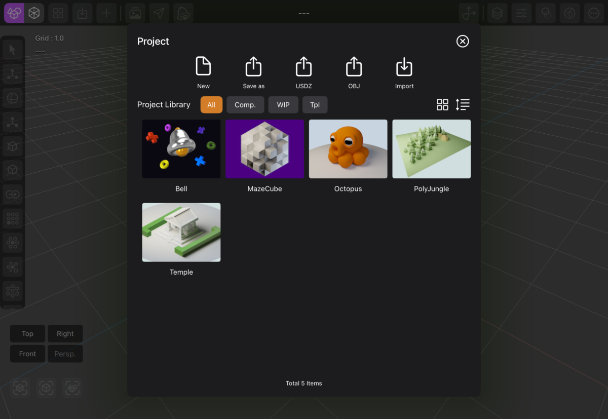
DGArt Project Library Interface.
Projects Features• New: Create a new project.
• Save As: Save the current project under a new name.
• USDZ: Save the current project in USDZ format.
- Exported files are saved in the "Export" folder via the Files app.
• OBJ: Export the selected object as an OBJ file.
- Exported files are saved in the "Export" folder via the Files app.
• Import: Import OBJ files into your project.
- Place the OBJ file in the "Import" folder via the Files app so the app can access it for import.
• All project files are accessible in the Files app.
• The "Projects" folder contains all project folders, including .scn files that can be used in the Playground app on iPadOS or Xcode on macOS.
• Project Library Views
• All: Displays all projects.
• Comp: Lists completed projects (rendered images saved).
• WIP: Lists projects marked as Work In Progress.
• Tpl: Lists template projects (project names ending with -tpl) used for quick access or appending frequently used items like lighting setups or backdrops.
• Thumbnail Size – Toggle between large and small thumbnail views.
• Sort – Sort project names in ascending or descending order.
• Long Press – Long press on a project thumbnail to rename, delete, or append items from that project.
Scene
 Layer Panel
Layer PanelHide/Unhide Object: Tap the visibility icon to toggle the object's visibility in the scene.
Delete Object: Tap the delete icon to remove the selected object from the scene.
Parent/Unparent Object:
• Action: Swipe right on the object entry and tap Make Child to parent or unparent objects in the hierarchy.
• Alternatively, drag and drop an object entry onto another to make it a child.
Set/Save as Custom Object:
• Action: Swipe left on the object entry, then tap the "Custom Object" to designate it as a custom object.
Set Active Camera:
• Action: Swipe left on a camera object, then tap the "Set Active" button to make it the current active camera in the scene.
 Property Panel
Property Panel• Object Properties: Precisely adjust object attributes such as position, rotation, scale, and more.
• Lighting Parameters: Configure lighting settings including color, intensity, and other relevant properties.
• Camera Parameters: Set camera options such as focal length, field of view (FOV), depth of field (DoF), and additional camera-specific settings.
 Material Panel
Material Panel• Material Properties: Customize object materials by adjusting attributes such as base color, metalness, and illumination.
• Special Effects: Configure advanced surface effects, including specular, shininess, normal mapping, emission, transparency, and refraction index.
Rendering Options:
• Toggle Double-Sided rendering.
• Enable or disable Smooth Shading.
• Set the Cull Mode to control which faces are rendered (e.g., front, back, or both).
 Environment Panel
Environment PanelAdjust scene settings including:
• Background Color
• Lighting Environment
• Fog (color, density, range)
• Reflection Settings (intensity, blur, etc.)
Custom Objects
• Custom objects can speed up your modeling process by allowing access to your own object library.• By adding frequently used objects into the scene or modeling process, you can enhance efficiency.
• Custom objects are stored in the Files app in OBJ format, under the DGArt/CustomObjects folder.
Append Objects
• Append objects, lights, and cameras from another project to increase productivity.• In the project panel, long-press the selected project, then select "Append" from the menu. Choose any item from the item library.
Points Clone
• Select the object to be cloned.• Shift-select the reference object.
• Tap on "Points Clone".
• Adjust parameters as needed.
Animation Basic
Animate Light
Animate Visibility
Animate Morph
• Prepare basic objects such as the Floor and the Object before proceeding.• Clone and edit the morph object, ensuring its name includes the original name followed by a dash and the morph name (e.g., name-morph1).
• Select the original object, go to the Properties panel, and add the morph object.
• The morph key will then appear in the timeline.
 RT:Render
Press the Render button to start the rendering process. Wait until the image becomes clear and noise is
reduced. Then, press Pause and save the image. The rendered image will be saved directly to your camera roll.
Modeler
 Select
• In the Modeler – Polygon/Point Edit Mode.• Select a polygon or point.
• Disable "Select" to enable navigation mode.
• Use various selection tools as needed.
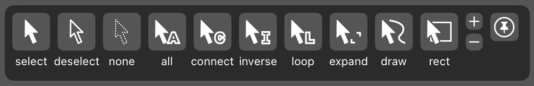
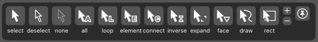 Polygon Selection Tools (from left to right):
• Select – When enabled, allows selection of multiple polygons.
• Deselect – Deselect a single or multiple polygons.
• None – Deselects all polygons.
• All – Selects all polygons.
• Loop – Select two nearby polygons to auto-select a loop (ring selection).
• Element – Select polygons by element or material.
• Connect – Select all connected polygons.
• Inverse – Invert the current polygon selection.
• Expand – Expand the selection to neighboring polygons.
• Face – Select by face type (e.g., select only triangle polygons).
• Draw – Freehand draw on the screen to select polygons.
• Rect – Draw a rectangular area on the screen to select polygons.
 Point Selection Tools (from left to right):
• Select – When enabled, allows selection of multiple points.
• Deselect – Deselect a single or multiple points.
• None – Deselects all points.
• All – Selects all points.
• Connect – Select all connected points.
• Inverse – Invert the current point selection.
• Loop – Select two nearby points to automatically select a loop (ring selection).
• Expand – Expand the selection to neighboring points.
• Draw – Freehand draw on the screen to select points.
• Rect – Draw a rectangular area on the screen to select points.
Additional UI Controls:
• The plus (+) and minus (−) icons apply only to Draw and Rect selection modes.
– When the plus icon is enabled, each new selection is added to the existing selection (accumulated).
• The pin icon pins the selection panel to stay visible on the screen.
Precision
DGArt Modeler PrecisionMake sure Show Precision Panel is turned on in the Settings page under the Modeler section.
In Modeler - Polygon or Point Edit Mode:
• The Precision panel is shown on the top right side and is active during selection mode.
• There are three main precision controls: Position, Bounding Box, and Center.
• Select a polygon or point, then set precision for Position (X, Y, Z).
• Select at least two points or polygons for Bounding Box precision (W, H, D).
• Select at least two points or polygons for Center precision (X, Y, Z).
 Move
Move
• In the Modeler - Polygon/Point Edit Mode.• Select a polygon or point and tap on "Move".
• Then, drag any icon handle to move the polygon or point.
• This operation supports multiple polygons or points.
 Rotate
• In the Modeler – Polygon/Point Edit Mode.• Select a polygon or point, then tap on "Rotate".
• Drag any handle icon to adjust the rotation.
• This operation supports multiple polygons or points.
• You can set the anchor point to either Local, Pivot mode or Part.
 Scale
Scale
• In the Modeler - Polygon/Point Edit Mode.• Select few polygons or points and tap on "Scale".
• Drag any handle to adjust the scale.
• You can set the anchor point to either Local, Pivot mode or Part.
 Polygon Extrude
• In the Modeler - Polygon Edit Mode.• Select a polygon and tap on "Extrude".
• Drag the icon to adjust the extrusion depth.
• This operation supports multiple face extrusions.
 Polygon Inset
• In the Modeler - Polygon Edit Mode.• Select a polygon and tap on "Poly Inset".
• Then drag the icon to adjust the inset value.
• This operation supports multiple faces.
 Polygon Bevel
• In the Modeler - Polygon Edit Mode.• Bevel works on connected objects.
• Adjust the edge width by dragging the slider.
 Polygon Loop Cut
• In the Modeler - Polygon Edit Mode.• Select two adjacent faces and tap on "Loop Cut".
• The looped face will be divided in half.
 Polygon Smooth Shift
• In the Modeler - Polygon Edit Mode.• Select connected multiple faces and tap on "Smooth Shift".
• Adjust the new faces from the top, right, or front view.
 Polygon Thicken
• In the Modeler - Polygon Edit Mode.• Make sure the polygons are not closed.
• Tap on "Thicken".
• Adjust the thickness as needed.
 Polygon Knife
• In the Modeler - Polygon Edit Mode.• Tap on "Knife".
• Cut the polygon from any view.
• Holding Shift while using the Knife tool snaps cuts to horizontal or vertical lines.
 Polygon Cap
• In the Modeler - Polygon Edit Mode.• Select a polygon.
• Tap on "Polygon Cap".
• Add caps to polygons using three different profile options, with segment and height control.
 Polygon Boolean
• In the Modeler - Polygon Edit Mode.• Boolean works on two separate objects.
• Select one object and make sure both are closed meshes.
• Choose the button for Subtract, Union, or Intersection.
 Polygon Bridge
• In the Modeler - Polygon Edit Mode.• Select two polygons that are close to each other.
• Ensure the selected faces are aligned.
• Tap on the "Bridge Poly" button to connect the polygons between the two selected faces.
• To create a hole, select two faces opposite each other,
• then tap on the "Bridge Poly" button. A hole will be created within the object.
 Polygon Catmull–Clark Subdivision Surface
• In the Modeler - Polygon Edit Mode.• Tap on Catmull–Clark Subdivision Surface.
• The polygons will be subdivided.
 Polygon Subdivision Surface
• In the Modeler - Polygon Edit Mode.• Tap on Subdivision Surface.
• The polygons will be subdivided.
 Polygon Lathe
• In the Modeler - Polygon Edit Mode:• Ensure there is only one polygon selected.
• Tap on "Lathe" to spin the polygon.
• Adjust the slider below to control the lathe’s side count.
• Choose the axis that suits your case: X, Y, or Z.
• Once done, tap on the Lathe icon to exit.
• If the polygon face is inverted, use the Poly Invert tool to fix it.
 Polygon Merge
• In the Modeler - Polygon Edit Mode.• Select polygons that are close to each other and merge them seamlessly.
 Polygon Flip
• In the Modeler - Polygon Edit Mode.• Select a polygon and flip its face normal inward or outward.
• This operation supports multiple faces.
 Polygon Make Pole
• In the Modeler - Polygon Edit Mode.• Select a polygon and tap on "Make Pole".
• This will generate new faces and a central vertex.
• This operation supports multiple faces.
 Polygon Rotate Face
• In the Modeler - Polygon Edit Mode.• Quad polygon faces are generated by two triangle faces,
• which may not appear planar if some of the vertices are not aligned in a plane.
• Use the "Rotate Face" function to rotate the face and achieve your desired polygon appearance.
• This operation supports multiple faces.
 Point Drag
• In the Modeler - Point Edit Mode.• Tap on "Point Drag" to drag and reposition any point on the screen.
• When mirror mode is on, the point on the opposite X value will update according to the point being dragged.
 Point Extend
• In the Modeler - Point Edit Mode.• Select the 2 nearest points.
• Tap on "Extend".
• Then drag and move the icon to reposition the new points.
 Point Snap Guide
• In the Modeler - Point Edit Mode:• Select multiple points and tap on "Snap Guide".
• Draw a guide on any axis, and the points will align to that guide.
• You can select either Freeform Line or Linear Line.
• While in Linear Line mode, holding Shift will snap the guide to the nearest vertical or horizontal line.
• Note: This function works in all views except Perspective and Orthographic views.
 Point Twist
• In the Modeler - Point Edit Mode.• Select multiple points, then tap on "Twist".
• Twist along the X, Y, or Z axis.
 Point Bend
• In the Modeler - Point Edit Mode.• Select multiple points, then tap on "Bend".
• Bend along the X, Y, or Z axis.
 Point Taper
• In the Modeler - Point Edit Mode.• Select multiple points, then tap on "Taper".
• Taper along the X, Y, or Z axis.
Point Stretch
• In the Modeler - Point Edit Mode.• Select multiple points, then tap on "Stretch".
• Stretch along the X, Y, or Z axis.
 Point Skew
• In the Modeler - Point Edit Mode.• Select multiple points and then tap on "Skew".
• Skew along the XY, YZ, or XZ axis.
 Point Vortex
• In the Modeler - Point Edit Mode.• Tap on "Vortex".
• Rotate along the Y, Y, or Z axis.
 Point Draw Poly
• In the Modeler - Point Edit Mode:• Tap on "Draw Poly" to draw a new face.
• Two options are available: touch-point draw mode and draw-paint mode.
• In touch-point draw mode, touch the screen and each point will be drawn.
• In draw-paint mode, draw on the screen to create any desired shape.
• Points drawn in a clockwise direction will generate an inward face.
• Points drawn in an anticlockwise direction will generate an outward face.
• Once the poly face is created, you can use the extrude tool to add depth to the poly face.
• If the shape is irregular, use the Split Poly and Smooth Shift tools to create depth.
 Point Make Poly
• In the Modeler - Point Edit Mode.• Select a minimum of 3 points and tap on "Make Poly" to create a new face.
• Point selection in a clockwise direction will generate an outward face,
• while point selection in an anticlockwise direction will generate an inward face.
 Split Polygon
• In the Modeler - Point Edit Mode.• Select 2 points in the polygon.
• Tap on Split Polygon.
• The polygon will be split automatically.
 Points Merge
• In the Modeler - Point Edit Mode.• Option 1
• Select the 2 nearest points.
• Tap on Points Merge.
• The points will be merged automatically.
• Option 2
• Tap Merge will merge any points that are close to each other.
 Points Randomize
• In the Modeler - Point Edit Mode.• Tap on Points Randomize.
• Adjust the value and select the X, Y, or Z axis.
 Points Edge Crease
• In the Modeler - Point Edit Mode.• Tap on Edge Crease.
• The edge crease value is used to control the sharpness of the edges in the subdivided mesh.
• The subdivision level will be set automatically to level 3.
Assign Material
• In the Modeler - Polygon Edit Mode.• Select any polygon and assign a new material to it.
• Switch back to Scene Mode and open the Material Panel.
• Set a color for each material.